Finite Impulse Response Filter
Overview
A Finite Impulse Response Filter works to filter data using a defined number of to data points to calculate an output (y-values) based on the current and previous inputs [x, x(n-1), x(n-2),... ]
Calculation - steps outline in 49 CFR 527.44 (d)
Apply Butterworth Filter at CFC 180
CFC is an impact testing standard created by the SAE J211 guidelines
Resample time step to 1600 Hz
Remove any bias present in resampled signal (offset from zero)
Calculate required parameters for Kaiser Window
A represents the stopband attenuation in dB
The 8 and 2.285 value used in the filter length equation is empirically derived for the Kaiser window
F i l t e r L e n g t h ( N ) = A − 8 2.285 ( s t o p b a n d f r e q u e n c y − p a s s b a n d f r e q u e n c y ) Filter\,Length\,(N) = \frac{A-8}{2.285(stopband\,frequency - passband\,frequency)} F i lt er L e n g t h ( N ) = 2.285 ( s t o p ban d f re q u e n cy − p a ss ban d f re q u e n cy ) A − 8 W i n d o w P a r a m e t e r ( B ) = { 0.1102 ∗ ( A − 8.7 ) , f o r A > 50 0.5842 ∗ ( A − 21 ) 0.4 + 0.07886 ∗ ( A − 21 ) , f o r 21 ≤ A ≤ 50 0 , f o r A < 21 Window\,Parameter(B) = \begin{cases} 0.1102*(A-8.7), for\,A>50 \\ 0.5842*(A-21)^{0.4}+0.07886*(A-21), for\,21 \le A \le 50\\ 0, for\, A < 21\end{cases} Win d o w P a r am e t er ( B ) = ⎩ ⎨ ⎧ 0.1102 ∗ ( A − 8.7 ) , f or A > 50 0.5842 ∗ ( A − 21 ) 0.4 + 0.07886 ∗ ( A − 21 ) , f or 21 ≤ A ≤ 50 0 , f or A < 21
Apply basic formula for ideal low-pass filter to Kaiser window (w(t))
I d e a l L o w P a s s F i l t e r ( h i d e a l ( t ) ) = s i n ( 2 p i ∗ ( c u t o f f f r e q u e n c y ) ∗ t ) p i ∗ t Ideal\,Low\,Pass\,Filter\,(h_{ideal}(t)) = \frac{sin(2pi*(cutoff\,frequency)*t)}{pi*t} I d e a l L o w P a ss F i lt er ( h i d e a l ( t )) = p i ∗ t s in ( 2 p i ∗ ( c u t o ff f re q u e n cy ) ∗ t ) I m p u l s e R e s p o n s e ( h ( t ) ) = h i d e a l ( t ) ∗ w ( t ) Impulse\,Response\,(h(t)) = h_{ideal}(t)*w(t) I m p u l se R es p o n se ( h ( t )) = h i d e a l ( t ) ∗ w ( t )
Calculate filter coefficients
In the equation below, n represents the sample index ranging from 0 to N-1
N represents the filter length
w(c) represents the Kaiser Window fucntion applied to the sinc function
F i l t e r C o e f f i c i e n t s ( h n ) = s i n ( 2 p i ∗ ( c u t o f f f r e q u e n c y ) ∗ ( n − N − 1 2 ) ) p i ∗ ( n − N − 1 2 ) ∗ w ( n ) Filter\,Coefficients\,(h_{n}) = \frac{sin(2pi*(cutoff\,frequency)*(n- \frac{N-1}{2}))}{pi*(n- \frac{N-1}{2})}*w(n_) F i lt er C oe ff i c i e n t s ( h n ) = p i ∗ ( n − 2 N − 1 ) s in ( 2 p i ∗ ( c u t o ff f re q u e n cy ) ∗ ( n − 2 N − 1 )) ∗ w ( n )
Calculate Kaiser window
K a i s e r W i n d o w ( w ( n ) ) = I o ( B 1 − ( 2 n N − 1 ) 2 ) I o ∗ B Kaiser\,Window\,(w(n)) = I_o \frac{(B \sqrt{1- (\frac{2n}{N-1})^2})}{I_o*B} K ai ser Win d o w ( w ( n )) = I o I o ∗ B ( B 1 − ( N − 1 2 n ) 2 )
Apply FIR filter, using calculated filter coefficients and Kaiser window, in both the forward and reverse direction to avoid phase distortion
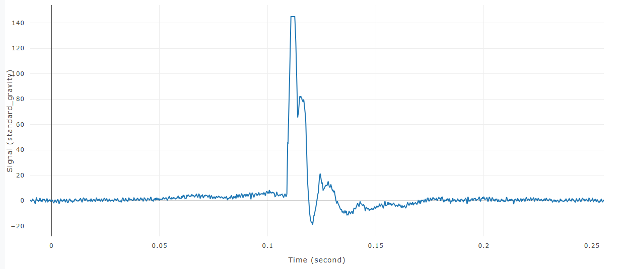
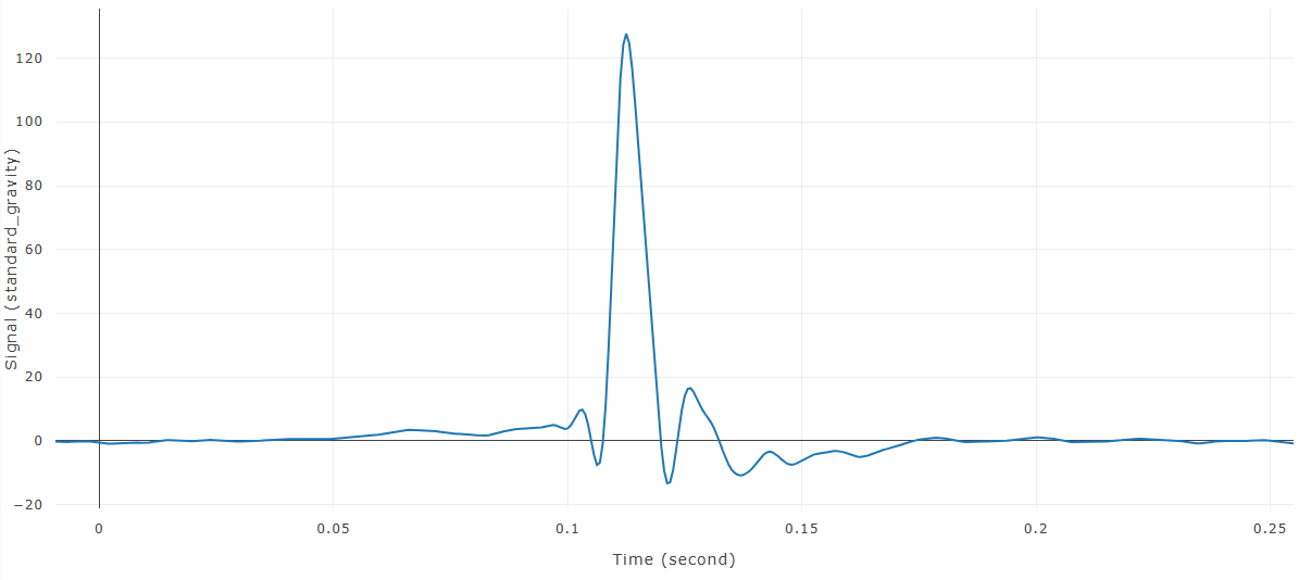
Finite Impulse Response Filter Example
Before FIR is applied to signal
After FIR is applied to signal